
Complete Car Stereo Wiring Guide: Colors, Harnesses, Interfaces & Troubleshooting
Car Stereo Wiring Guide
Learn how to connect a replacement receiver using the correct harnesses, interfaces, power and speaker wires, RCA signals, steering-wheel controls, antenna adapters, camera and USB retention parts, testing procedures and troubleshooting methods.
Confirm that battery disconnection will not create a radio-code, security-system or vehicle-memory issue.
Harnesses, interfaces and safe connections
1.1 Why Car Stereo Wire Colors Matter
Most aftermarket radios use a standardized color code for their primary power, control and speaker wires. Connector shape and wire count may vary by brand, but the common aftermarket functions are generally identified by familiar colors. Understanding each wire by function is more important than matching colors blindly.
The vehicle-specific harness and the radio harness should each include a wire legend. Verify the function listed on both harnesses before making a connection.
The factory vehicle wiring may use completely different colors. Match the vehicle-specific harness and receiver harness by their labeled functions, and verify any uncertain circuit before connecting it.
1.2 Use a Vehicle-Specific Harness Instead of Cutting Factory Wiring
Use a Harness – Recommended
- No factory wires need to be cut.
- The installation can usually be reversed.
- The original connector remains intact.
- Power, speaker and control functions are easier to identify.
- The risk of shorts and poor connections is reduced.
Cutting Factory Wiring – Not Recommended
- Can permanently damage the factory harness.
- Makes future service more difficult.
- Increases the chance of incorrect connections.
- Can create shorts, blown fuses or vehicle errors.
- May interfere with factory amplifiers and data systems.
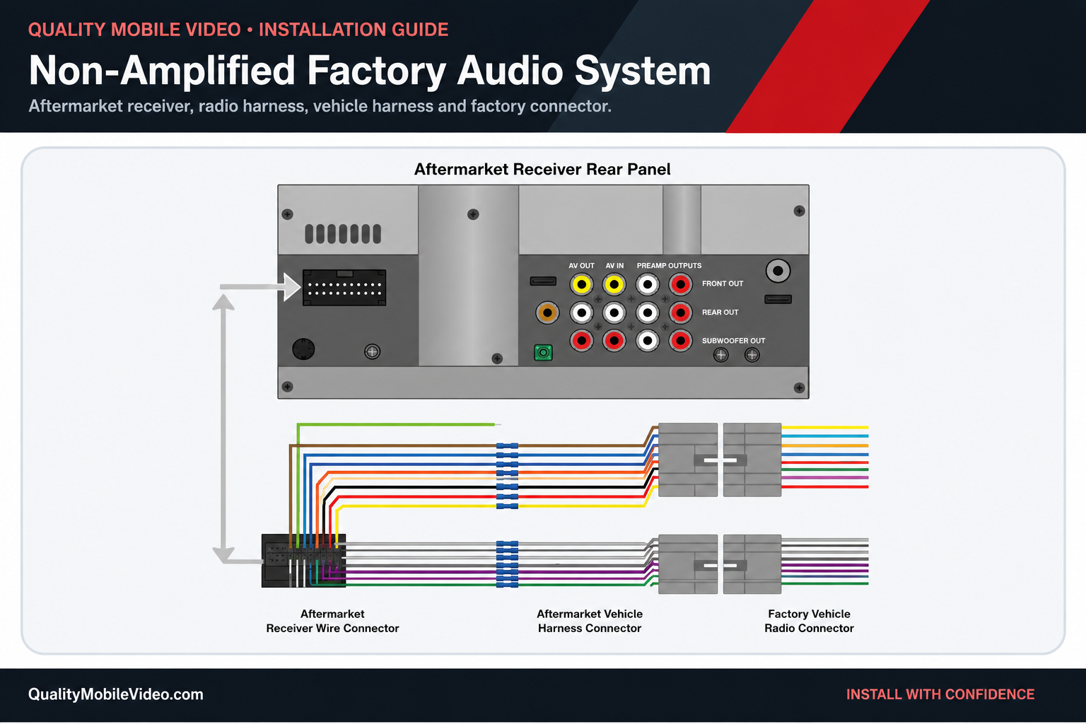
1.3 Does the Vehicle Need a Data Interface?
Many newer vehicles use a data-bus system to control accessory power, retained accessory power, warning chimes, factory amplifiers, steering-wheel controls, cameras and vehicle settings. A compatible interface converts those data commands into signals the replacement receiver can use.
Accessory Power
Creates a switched 12-volt output.
Factory Amplifier
Provides turn-on and audio integration.
Steering-Wheel Controls
Retains compatible factory buttons.
Warning Chimes
Retains alerts played through the radio.
Factory Camera
May retain or convert the camera signal.
Vehicle Settings
May retain settings accessed through the factory display.
Interface or Wiring Harness Selection Guide
Use this quick decision chart to determine whether your vehicle requires a basic wire harness or a data/feature-retention interface.
An interface is likely required.
Look for one or more of these factory features:
- Factory amplifier or premium audio system
- Steering-wheel audio controls
- Retained accessory power
- Warning chimes or safety alerts through the speakers
- Factory backup camera or USB port
- Vehicle settings displayed through the factory radio
- OnStar, SYNC, Uconnect or similar factory integration
A basic wiring harness may be sufficient.
A standard harness may work when the vehicle has:
- Conventional constant, accessory and ground wiring
- No factory amplifier
- No steering-wheel controls to retain
- No data-controlled chimes or retained features
- Direct speaker wiring from the radio
Final check: Enter the vehicle information at MetraOnline.com to verify whether the application requires a harness, data interface or feature-retention module.
1.4 Connect the Two Aftermarket Harnesses
- Lay out both harnesses. Separate power, control and speaker wires.
- Read both wire legends. Confirm every function.
- Join matching functions. Connect constant, accessory, ground and speaker pairs correctly.
- Insulate every connection. Use proper crimps or solder and heat shrink.
- Cap unused wires individually. Never leave exposed copper.
1.5 Required Tools and Installation Supplies
Having the correct tools reduces the chance of damaged panels, weak connections and incorrect circuit testing.
Use a high-impedance meter for power, signal and ground testing.
Shop this tool →Use only a probe designed for modern low-voltage vehicle electronics.
Shop this tool →Prepare conductors without nicking or removing excess wire.
Shop this tool →Use connectors sized correctly for the wire gauge.
Shop this tool →Use rosin-core solder and heat-shrink tubing when soldering.
Shop this tool →Plastic panel tools help prevent scratches and broken clips.
Shop this tool →Insulate, protect and bundle completed wiring connections.
Shop electrical tape →Provide durable insulation and strain relief for crimped or soldered connections.
Shop heat-shrink tubing →Secure wiring away from sharp edges, heat sources and moving parts.
Shop wire ties →Keep all wiring legends, interface guides and programming steps available.
Power Wires Explained
2.1 Power and Control Wire Overview
These wires power the receiver, determine when it turns on, retain memory, control external amplifiers and antennas, and communicate illumination, parking-brake, reverse and vehicle-speed signals.
| Wire Color | Typical Function | When It Has Power or Signal | Basic Test |
|---|---|---|---|
| Yellow | Constant 12-volt battery power | At all times | Approximately 12 volts with the key OFF, in ACC and with the engine running |
| Red | Accessory or ignition 12 volts | When the key is in ACC or ON | 0 volts with the key OFF and approximately 12 volts in ACC or ON |
| Black | Ground | Ground reference at all times | Very low resistance to verified chassis ground with battery power disconnected |
| Blue | Power antenna | Typically while AM/FM is selected | Approximately 12 volts while the radio tuner is active |
| Blue/White | Amplifier remote turn-on | Whenever the receiver is on | Approximately 12 volts whenever the receiver is powered on |
| Orange | Illumination | When exterior lights are on | 0 volts with lights OFF and approximately 12 volts with lights ON |
| Orange/White | Dimmer or variable illumination | Changes with the dimmer control on applicable vehicles | Voltage may vary as the dimmer is adjusted |
| Brown | Mute input on some receivers | Only when an external device commands mute | Follow the receiver manual because this function is not universal |
| Light Green | Parking-brake input | When the parking brake is applied, depending on receiver design | Verify required polarity and sequence in the receiver manual |
| Violet/White | Reverse trigger | When the transmission is placed in reverse | Approximately 12 volts in reverse on common positive-trigger systems |
| Pink | Vehicle-speed signal on some receivers | Pulsed signal while the vehicle is moving | Test only with suitable equipment and vehicle-specific information |
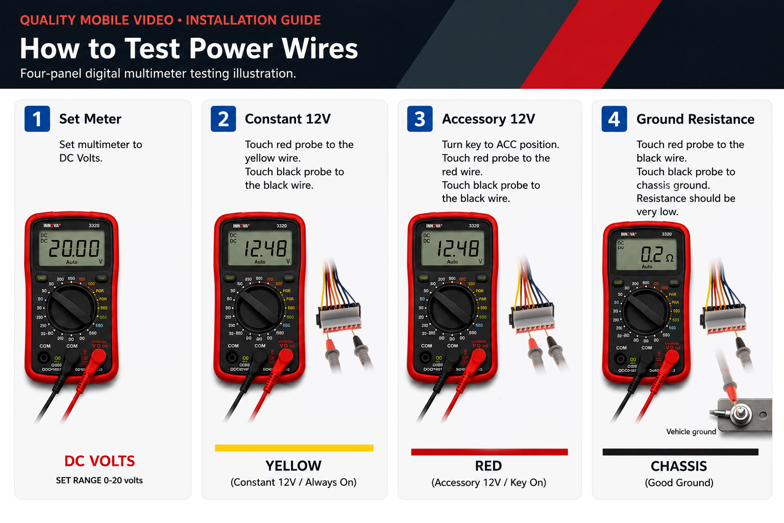
2.2 How to Test Power Wires with a Digital Multimeter
Use the correct vehicle information and a high-impedance digital multimeter or approved electronic probe.
Test Constant 12 Volts
- Set the meter to DC voltage.
- Connect the black probe to verified ground.
- Touch the red probe to the suspected yellow wire.
- It should read about 12 volts in every key position.
Test Accessory 12 Volts
- Keep the black probe on verified ground.
- Test the suspected red wire with the key OFF.
- The reading should be near 0 volts.
- Turn the key to ACC or ON; it should rise to about 12 volts.
Test Ground
- Disconnect battery power before resistance testing.
- Set the meter to continuity or resistance.
- Probe the ground wire and clean chassis metal.
- A very low corrected resistance indicates a strong ground path.
Test Remote Turn-On
- Reconnect the receiver safely and turn it on.
- Test blue/white referenced to ground.
- It should provide about 12 volts whenever the receiver is on.
- Solid blue may turn off on non-radio sources.
2.3 Common Power-Wire Mistakes
- Reversing yellow and red: The receiver may lose memory or fail to operate correctly.
- Using a poor ground: Can cause intermittent operation, dimming, noise or no power.
- Using solid blue for an amplifier: The amplifier may shut off when Bluetooth, USB or another source is selected.
- Leaving unused wires exposed: An exposed conductor can short to the radio chassis or another wire.
- Failing to fuse an added circuit: Protect any added power lead with an appropriately sized fuse near its source.
Front and Rear Speaker and Signal Wires
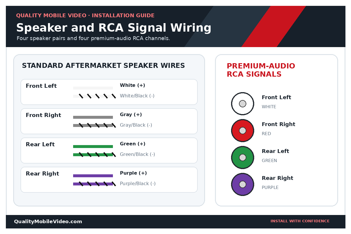
3.1 Standard Aftermarket Speaker-Wire Colors
Aftermarket receivers commonly use four color groups for the four speaker locations. The solid-color wire is normally positive and the same color with a black stripe is normally negative.
| Speaker | Positive (+) | Negative (-) |
|---|---|---|
| Front Left | White | White/Black |
| Front Right | Gray | Gray/Black |
| Rear Left | Green | Green/Black |
| Rear Right | Purple | Purple/Black |
Four-Channel RCA Signals Used by Some Factory-Audio Interfaces
Some harnesses and interfaces for premium or upgraded factory systems provide four low-level RCA outputs instead of conventional speaker-level wires.
| Channel | RCA Barrel | Connection |
|---|---|---|
| Front Left | White | Connect to the receiver Front Left preamp output |
| Front Right | Red | Connect to the receiver Front Right preamp output |
| Rear Left | Green | Connect to the receiver Rear Left preamp output |
| Rear Right | Purple | Connect to the receiver Rear Right preamp output |
3.2 Speaker Polarity and Phase
Each speaker has a positive and negative terminal. Every speaker should be connected with consistent polarity. Reversing one speaker may not damage it, but it can cause acoustic cancellation, weak bass, a hollow sound and poor stereo imaging.
Correct Polarity
- Fuller bass response
- More stable center image
- Consistent output between speakers
- Better overall clarity
One Speaker Reversed
- Weak or inconsistent bass
- Hollow-sounding vocals
- Poor stereo imaging
- Sound changes with seating position
3.3 Do Not Ground Speaker Negative Wires
Most modern aftermarket receivers use bridged speaker outputs. The negative speaker wires are active amplifier outputs and must not be connected to chassis ground or combined with other speaker negatives.
Grounding or combining speaker outputs can damage the receiver’s internal amplifier.
3.4 Factory Amplified Systems
If the vehicle has a factory amplifier, the replacement receiver may not connect directly to the speakers. The installation may require an amplifier-integration harness, data interface, level adapter or amplifier bypass. A receiver that powers up with no sound often indicates that the factory amplifier is not receiving the correct turn-on signal or audio input.
3.5 RCA Outputs and Amplifier Remote Turn-On
When an external amplifier is used, audio normally travels through RCA cables from the receiver’s preamp outputs. The blue/white remote wire supplies the low-current 12-volt signal that tells the amplifier to turn on.
- Use the correct front, rear and subwoofer RCA outputs.
- Connect blue/white to the amplifier remote terminal.
- Do not use the remote wire to power the amplifier itself.
- Route signal cables away from high-current power wiring when practical.
Steering-Wheel Controls & the Metra AXSWC-2 Interface
The AXSWC-2 Steering Wheel Control Data Interface automatically detects many vehicles and connected radios, presets controls, retains settings in non-volatile memory, provides LED feedback, supports manual programming, allows button remapping and dual assignment, and can be updated for current applications.
Keep your factory steering-wheel audio controls when installing a compatible aftermarket receiver.
Shop the Metra AXSWC-2 Steering Wheel Control InterfaceConfirm Compatibility
Use Metra’s vehicle fit guide and vehicle-specific instructions.
Verify Receiver Input
The radio must have a compatible wired or 3.5 mm steering-wheel-control input.
Follow Vehicle Wiring
Do not assume every vehicle uses the same SWC wires or data connection.
Program and Test
Confirm LED feedback and test every button before dash reassembly.
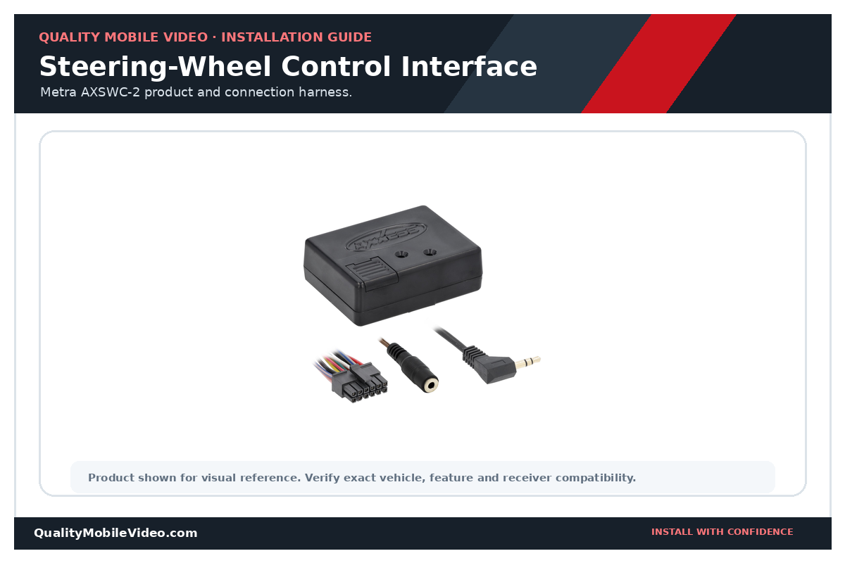
View AXSWC-2 product documents and installation instructions at MetraOnline.com.
Antenna, Camera and USB Adapters
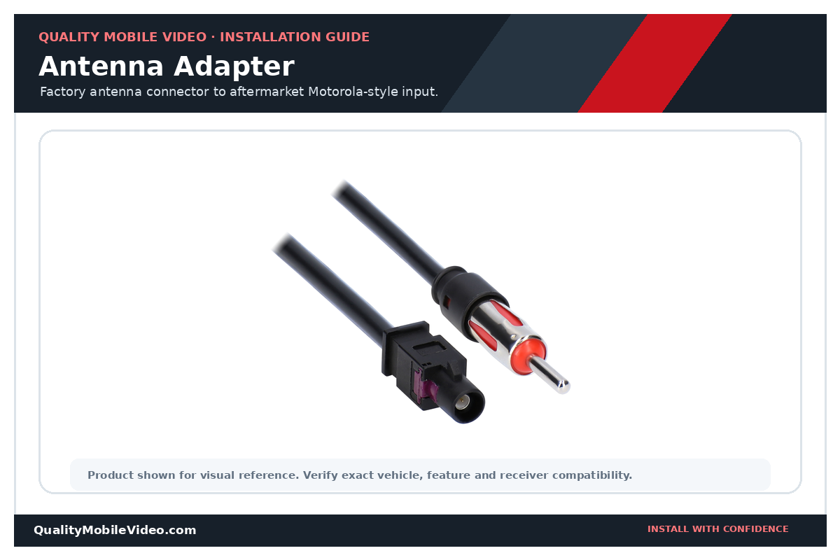
5.1 Antenna Adapters
The vehicle factory antenna connector may not fit the standard Motorola input plug on the aftermarket receiver. An antenna adapter converts the factory connector to an aftermarket antenna connector. Some amplified antenna systems also require a power lead, and the correct harness will have a lead to power the antenna amplifier. Visit MetraOnline.com for the correct adapter for your vehicle.
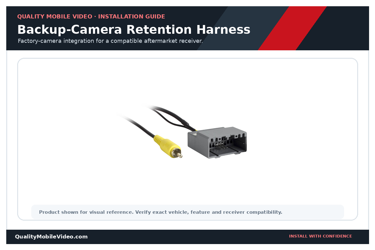
5.2 Backup-Camera Retention Harnesses
A compatible backup-camera retention harness can preserve the original camera connector and convert the camera voltage when required. The harness provides composite video through an RCA connector and passes the reverse trigger. Camera voltage and compatibility are vehicle-specific. Visit MetraOnline.com for the correct camera-retention harness for your vehicle.
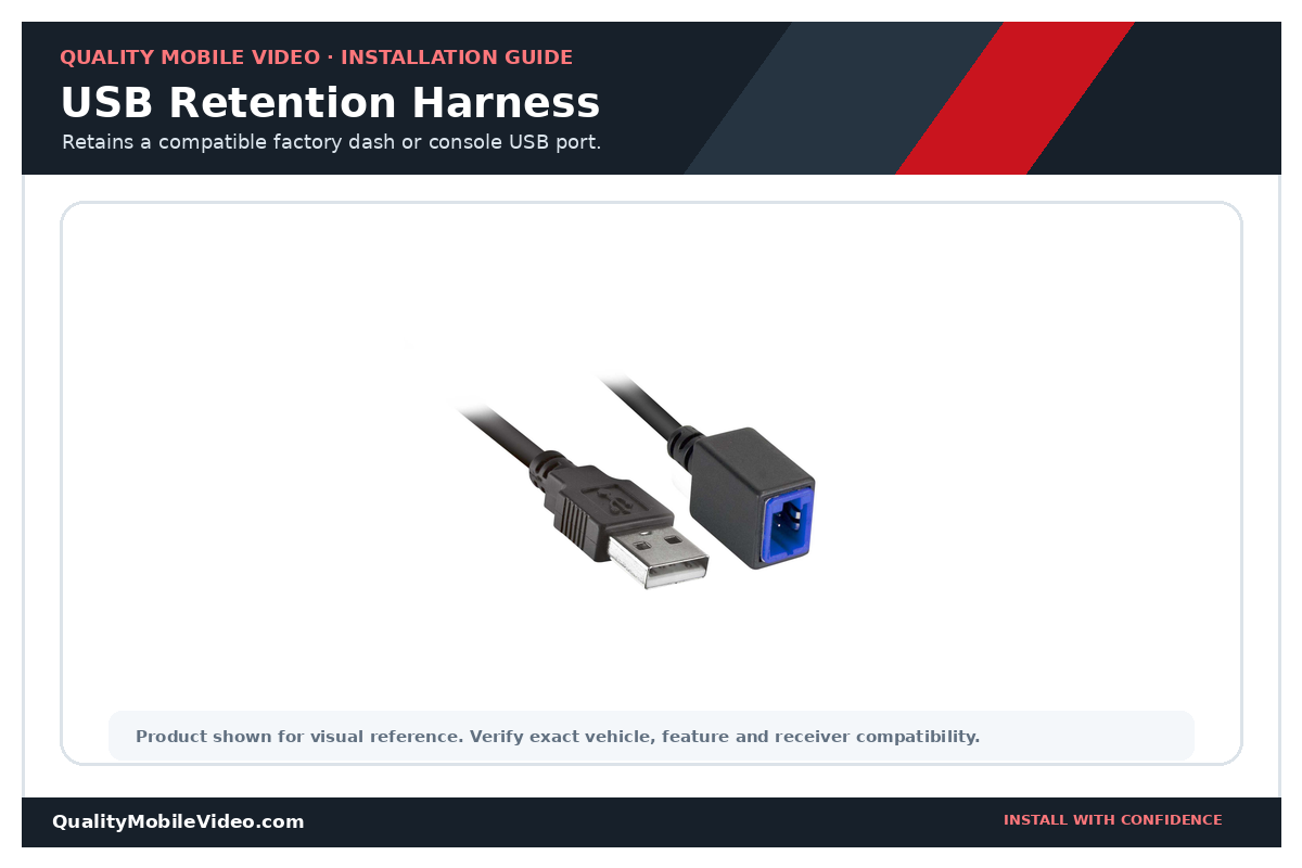
5.3 USB Retention Harnesses
A USB retention harness adapts the factory dash or console USB connector to a compatible replacement receiver. Depending on the application, it may retain charging, audio, data or only selected functions. Visit MetraOnline.com for the correct USB-retention harness for your vehicle.
Troubleshooting Guide
6.1 The Radio Does Not Turn On
- Verify constant 12 volts on yellow.
- Verify accessory 12 volts on red in ACC or ON.
- Verify black ground.
- Check receiver and vehicle fuses.
- Confirm required interface connections and programming.
- Inspect every crimp or solder connection.
6.2 The Radio Loses Memory or Presets
The yellow constant-power circuit is missing, intermittent or connected to a switched source. It should remain at approximately 12 volts with the key removed.
6.3 The Radio Turns On but There Is No Sound
- The factory amplifier may not be turning on.
- The blue/white remote wire may be disconnected or connected to the power-antenna output.
- An amplifier-integration interface may be required or may need programming.
- Speaker wires may be connected incorrectly, shorted or grounded.
- RCA cables may be connected to the wrong outputs.
- Check the receiver’s own fuse. Many aftermarket radios have a fuse installed in the rear chassis or inline with the receiver harness. A radio may illuminate or partially operate while an internal audio circuit remains unpowered, depending on the receiver design.
- Inspect the brown mute wire. On receivers that include a mute input, grounding or activating the brown wire tells the radio to mute its speaker and preamp outputs. If the brown wire is connected incorrectly, pinched against metal or left with exposed copper, the receiver may power on normally but produce no sound. Cap the wire individually when it is not used and verify the receiver’s wire legend.
- The receiver may be muted, faded or balanced away from the connected speakers.
6.4 The Amplifier Works on Radio but Shuts Off on Bluetooth or USB
The amplifier is probably connected to solid-blue power antenna rather than blue/white amplifier remote output.
6.5 Weak Bass or Hollow Sound
One or more speakers may have reversed polarity. Verify every positive and negative pair.
6.6 Alternator Whine or Electrical Noise
- Confirm radio and amplifier grounds are secure on clean metal.
- Check RCA cables for damage.
- Route RCA cables away from large power wires when practical.
- Verify no speaker negative is grounded.
- Check amplifier gain and the charging system.
- Do not use a ground-loop isolator instead of repairing the wiring fault.
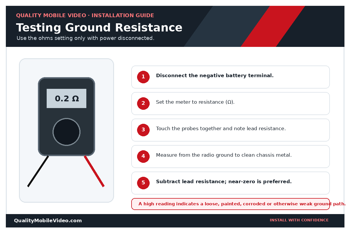
6.7 How to Test Ground Resistance with a Multimeter
- Disconnect the battery. Never measure resistance on a powered circuit.
- Set the meter to ohms. Use the lowest practical range.
- Measure the leads. Touch probes together and record lead resistance.
- Measure the ground path. Probe radio ground and verified clean chassis metal.
- Subtract lead resistance. Near zero is preferred; a higher reading indicates a weak, painted, loose or corroded connection.
6.8 The Backup Camera Does Not Switch Automatically
Verify camera accessory power, camera ground, video connection, the receiver reverse input and camera settings.
6.9 Steering-Wheel Controls Do Not Work
Verify interface compatibility, the correct radio input, vehicle-specific wiring, receiver selection and programming.
FAQs, Checklist and Installation Tips
7.1 Frequently Asked Questions
Are aftermarket radio wire colors universal?
They are commonly standardized but not guaranteed. Always confirm each function using the labels and installation manuals supplied with the receiver and vehicle-specific harness.
Should I solder or crimp the harness connections?
Either method can work when performed correctly. Use properly sized quality crimp connectors or soldered joints protected with heat-shrink tubing.
Can I twist the wires together and cover them with tape?
No. Twisted-and-taped connections can loosen, oxidize or short. Use a proper crimp or soldered connection and insulate it correctly.
Can I connect the blue wire to an amplifier?
Use the blue/white amplifier remote output unless the receiver instructions state otherwise. Solid blue may only remain active while the tuner is selected.
Why does my radio lose its settings?
The constant-power wire is missing, intermittent or connected incorrectly. Verify approximately 12 volts on yellow at all times.
Why does the radio turn on but produce no sound?
Common causes include a factory amplifier that is not turning on, a missing interface, incorrect speaker wiring, muted audio or RCA cables connected to the wrong outputs.
Can speaker negative wires be connected to chassis ground?
No. Modern receiver outputs are generally bridged. Each negative speaker conductor must remain isolated.
Do I need an interface for every vehicle?
No. Some vehicles only require a basic harness, while others require a data interface to create accessory power or retain factory features. Check MetraOnline.com and enter your specific year, make, model and factory audio system.
Can I use a test light?
A conventional test light completes a circuit and can place a load on sensitive low-voltage electronics. Testing the wrong wire may damage a control module and could affect an airbag circuit. Use correct vehicle wiring information and a high-impedance electronic meter or approved test probe instead.
Can I use a test probe?
Yes, provided it is an electronic, high-impedance automotive test probe that is designed for modern vehicle electronics. Verify the type of probe before testing any circuit.
How should I power an aftermarket backup camera?
Power the camera from a fused accessory circuit at the aftermarket video receiver so the camera is available whenever the receiver is on. Connect the positive reverse-lamp signal to the receiver’s reverse-input wire so the receiver switches automatically to the camera image when reverse is selected. Some vehicles use pulse-width modulation on the reverse-lamp circuit. In those applications, use a properly wired relay or a compatible PWM backup-camera stabilizer to provide a clean trigger or camera-power source. View PWM backup-camera stabilizer
Can Quality Mobile Video pre-wire a harness or interface for me?
Yes. We offer a pre-wiring service when the compatible harness or interface and the replacement receiver are purchased together. Please call for compatibility, pricing and ordering information.
7.2 Installation Checklist
Use the checklist below on-screen or download the one-page printable version for the installation bay.
Download the Printable Installation Checklist PDFBefore Installation
- Confirm exact year, make, model and factory audio system.
- Obtain dash kit, harness, antenna adapter and interface.
- Read all instructions.
- Check battery-disconnection requirements.
- Gather meter, wire tools, connectors and trim tools.
During Installation
- Disconnect the negative battery terminal.
- Match every wire by function.
- Secure and insulate every connection.
- Cap unused wires separately.
- Keep wiring clear of sharp edges and moving parts.
Before Reassembly
- Test power and memory.
- Test all four speakers and RCA channels.
- Test factory amplifier, camera and steering-wheel controls.
- Test illumination, dimmer and reverse functions.
- Confirm no warning lights or vehicle errors.
Final Inspection
- Bundle excess wire without crushing it.
- Secure the receiver and dash kit.
- Save wiring diagrams and instructions.
- Record custom changes.
- Reconnect the negative battery terminal.
7.3 Final Installation Tips
- Never assume vehicle wire colors match aftermarket wire colors.
- Use a vehicle-specific harness or interface whenever one is available.
- Reconnect the negative terminal of the battery after all wiring is inspected and secured.
- Verify each circuit before connecting it.
- Do not probe data wires without correct vehicle information and equipment.
- Test every function before reinstalling the dashboard.
Car Stereo Installation Essentials
Complete the installation with the correct vehicle adapters, wiring supplies and tools.
