Subwoofer Impedance and amplifier output
Ohms law

In electrical circuits there are two concepts. These concepts have a mathematical relationship between them.
I’ll use plumbing terms as it is easier to visualize these concepts using a pipe. The first is the voltage, in plumbing terms, voltage is the size of the pipe. The other is current or flow, in plumbing terms this is the pressure. These two concepts define the work or wattage.
Ohms law: V= I x R
V = Voltage
I = Current; measured in Milli-amps or Amps
R = Resistance; measured in Ohms
Using this concept and amplifier that outputs 400 watts at 4 Ohms will output 800 watts at 2 Ohms.
Speakers or Sub-woofers

Sub-woofers and speakers have a voice-coil; it is the heart or the device that performs the work. A voice-coil is a tightly wound copper wire that when electricity is applied, generates a magnetic field that either attracts or repels a closely mounted magnet.
When electricity is is moved through this copper wire it does so with resistance (known as Impedance), this resistance is measured in Ohms. The lower a speakers impedance, the easier it is drive.
Amplifier output relationship to Impedance
Amplifiers have a sweet spot in their relationship to output and impedance. Problems arise when a sub-woofer has very low impedance or resistance. The output of an amplifier is measured in wattage or work, work has a byproduct called heat. Excessive heat causes and amplifier to shut down to protect itself from destruction. Heat is the largest factor in the life span of electronics.
Consideration must be taken to factor what an amplifier output is capable of and the load you are introducing. Manufacturers clearly state what their amplifiers are capable of in output and in what situations or configurations. Car audio amplifiers are capable of driving a 4 ohm load. 4 ohms is what most car speakers and sub-woofers are rated at. Most car amplifiers are also capable of driving 2 ohm loads on a single channel.

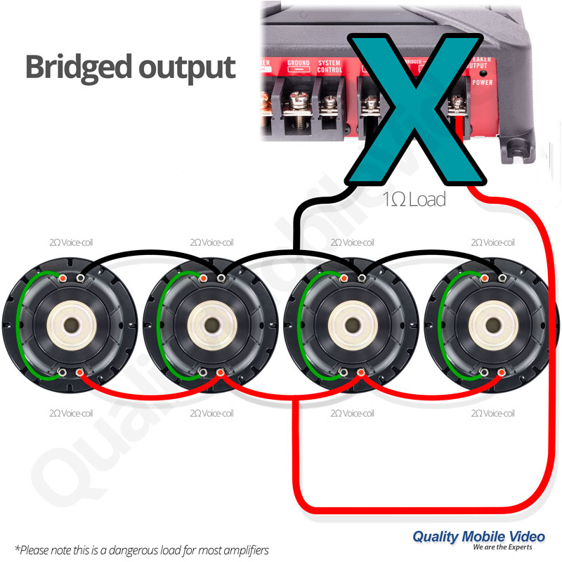
The most common error is when an amplifier is bridged, bridged operation utilizes two of the amplifiers channels and sums them together to provide more output. When an amplifier is bridged, its sees half of the load, or in the case of a 2 ohm woofer, 1 ohm. Most amplifiers are not capable of driving this low resistance as it would cause the amplifier to run extremely hot.
Single voice-coil and wiring options
Example: Paralleled connection
Paralleled configuration means the positive side of one voice-coil and the positive side of the other voice-coil to the positive side of the amplifier. The same connections would be made to the negative side, negative side of one voice-coil and the negative side of the other voice-coil to the negative side of the amplifier.
In this diagram we show you what is potentially a damaging load for most amplifiers. When paralleling dual 2 ohm voice-coils, this creates a load at the amplifier of only 1 ohm. 1 ohm loads for most amplifiers are catastrophic, please check with your amplifier manufacturer before connecting a sub-woofer to the output terminals
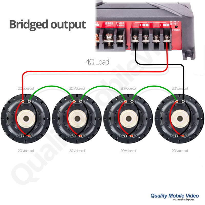
Example: Series output
Series configuration means that the sub-woofers are wire one after the other. The plus of woofer 1 to the minus of woofer 2, the remaining plus and minus are connected to the amplifier.
In this diagram we show you a load that is safe for most amplifiers. When connecting two 2 ohm voice coils in series you create a 4 ohm load. In a bridged operation this is safe for most amplifiers.
Multiple voice-coils and wiring options
In the examples above we were only talking about a single woofer and single voice coil. When we add multiple sub-woofers we can create different loads or resistance on the the amplifier. The sole reason for driving different loads is to optimize the amplifier to the amount of speakers.
Sub-woofers with dual voice coils have two connections and allow for different wiring options. This is especially useful in system design and allow for more flexibility. A dual 2 ohm woofer can be wired as a 4 ohm in series or 1 ohm in parallel. You can see this allows us a ton of flexibility when doing multi-speaker systems.
When we want massive bass the output of two woofers helps create the system we desire. When using multiple sub-woofers we must consider what the amplifier is capable of and the impedance implications that the multiple woofers present.
When speakers are in series, you add the speaker impedances together for the total impedance. One 4 ohm woofer wired in series to another 4 ohm woofer sums to a total impedance of 8 ohms.
When speakers are wired in parallel, provided they are of equal impedance, you divide the impedance by the amount of woofers. One 4 ohm woofer wired in parallel to another 4 ohm woofer has a total impedance of 2 ohms. Another example is when four 4 ohm woofers are wired in parallel the total impedance is 1 ohm.
3 Dual Voice Coil Sub-woofer Setup Example – 2.6 ohm load
Example 1: If we wanted three dual voice coil woofers in our system, and each woofer were dual 4 ohm coils we can wire this so that each woofer has its coils wired in series or 8 ohms each, and each woofer wired in parallel to the others so that the amplifier would see 2.6 ohms.
4 Dual Voice Coil Sub-woofer Setup Example – 1ohm load
Example 2: In this example we will take four dual 2 ohm woofers. We will wire each woofers coils in series making it a 4 ohm woofer, we will then connect them to the other woofers in parallel, the total impedance is 1 ohm for this system.
4 Dual Voice Coil Sub-woofer Setup Example – 4ohm load
Example 3: In this example we will take four dual 2 ohm woofers. We will wire each woofers coils in parallel so each woofer is 1 ohm. We will the wire each woofer in series to the other, the total impedance is 4 ohms.
This allows us to properly match the amplifier with the amount of woofers we want for the desired output. Consideration must be taken to ensure that the amplifier has the output capability to drive these multi-woofer systems. If each woofer is capable of 200 watts and we have three woofers we want to ensure that out amplifier has at least 600 watts of output. It is vitally important that we figure RMS ratings in these estimations as these are real world outputs and ratings. Multi-woofer systems that are underpowered will suffer from poor sound quality and possible damage as you exceed the output capabilities of the amplifier. Exceeding output capability causes the amplifier to clip and has the possibility to damage your woofers. The safer route is to have a slightly overpowered amplifier as it allows for more capability or headroom. This headroom prevents distortion when peaks of music occur and provide excellent sound quality as there is power on reserve for these impactful moments.
4 Dual Voice Coil Sub-woofer Setup Example – 4ohm load
In this photo we have the voice-coil as it should look when it is in new condition. Here you can see the tightly wound copper coil and the copper varnish is not discolored.
Burnt Voice-coil with broken former
This photo clearly demonstrated a damaged voice-coil former and damaged coil. The coil varnish is severely discolored which demonstrates excessive heat caused by distortion. Excessive heat causes the voice coil to separate thereby destroying the woofer.
Burnt Voice-coil with broken former
This photo clearly demonstrates the severely discolored coil varnish. It’s easy to see the charred remains and the unwinding.
The bottom line is we want a sub-woofer and it’s amplifier to have very similar ratings. We want the amplifier output capability to match the woofer input capability at its impedance rating. By doing so we ensure that we have a well powered system and one that was designed with excellent efficiency.


I have a Ford Escape 2007 w no auxiliary input and would like to get input it on How I how go about getting auxiliary input and a nice sounding system