
Two DVC Subwoofer Parallel Wiring Diagrams
Two DVC Subwoofer Parallel Wiring Diagrams
Choose the impedance of each voice coil to see how two dual-voice-coil subwoofers can be wired in parallel for a 0.5-ohm or 1-ohm final amplifier load.
GUIDES
Find the correct parallel-wiring diagram
Each dual-voice-coil subwoofer has two separate voice coils. With two matching DVC subwoofers, the circuit contains four identical coils. When every positive terminal is connected together and every negative terminal is connected together, all four coils are in parallel. Select the diagram that matches the impedance printed on each voice coil—not the desired final load.
Before selecting a diagram: Confirm that both subwoofers are matching DVC models and verify whether each voice coil is rated at 2 ohms or 4 ohms.
Choose a parallel-wiring guide
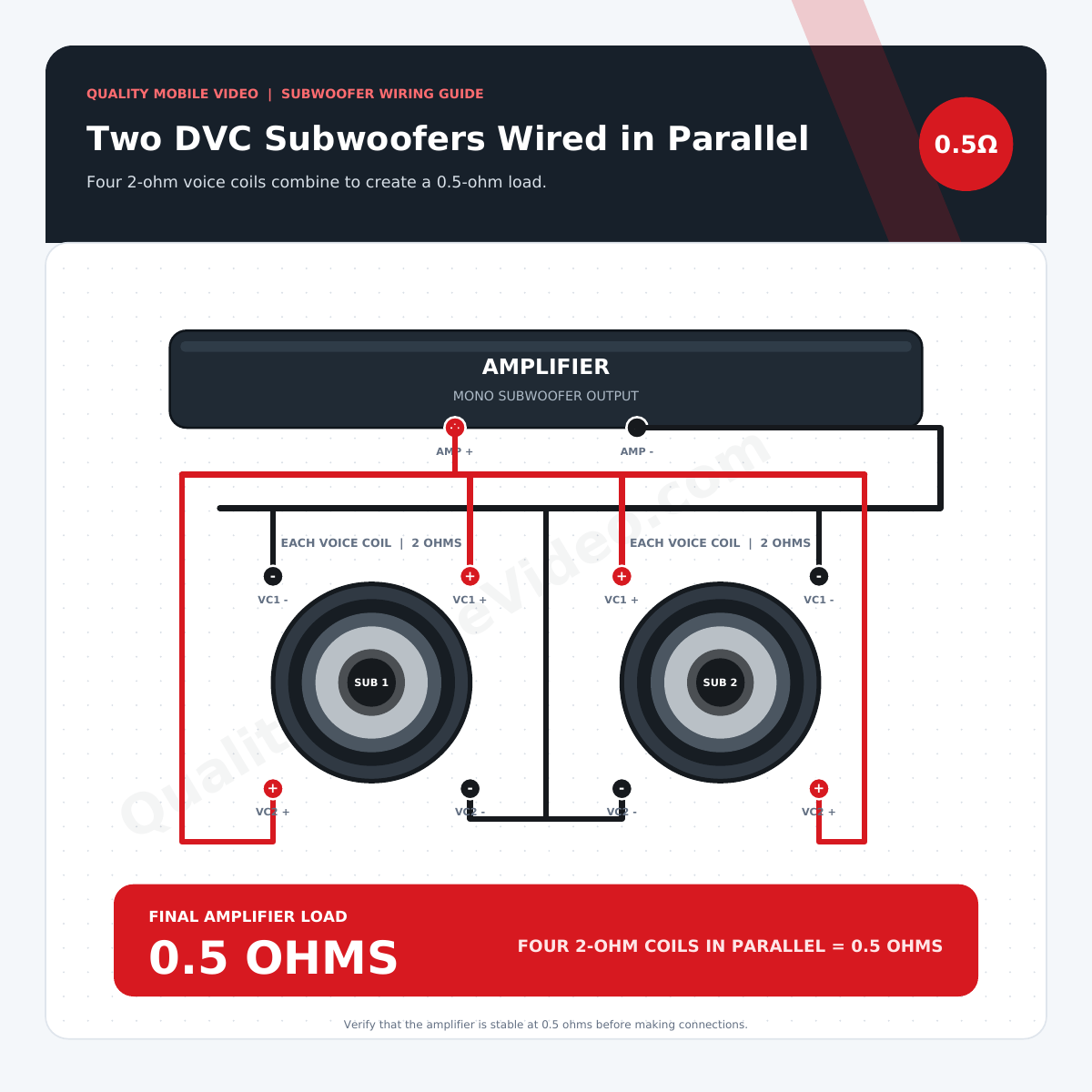
Four 2-Ohm Coils in Parallel
Wire all four 2-ohm voice coils in parallel to present a nominal 0.5-ohm load to the amplifier.
View the 0.5-ohm guide →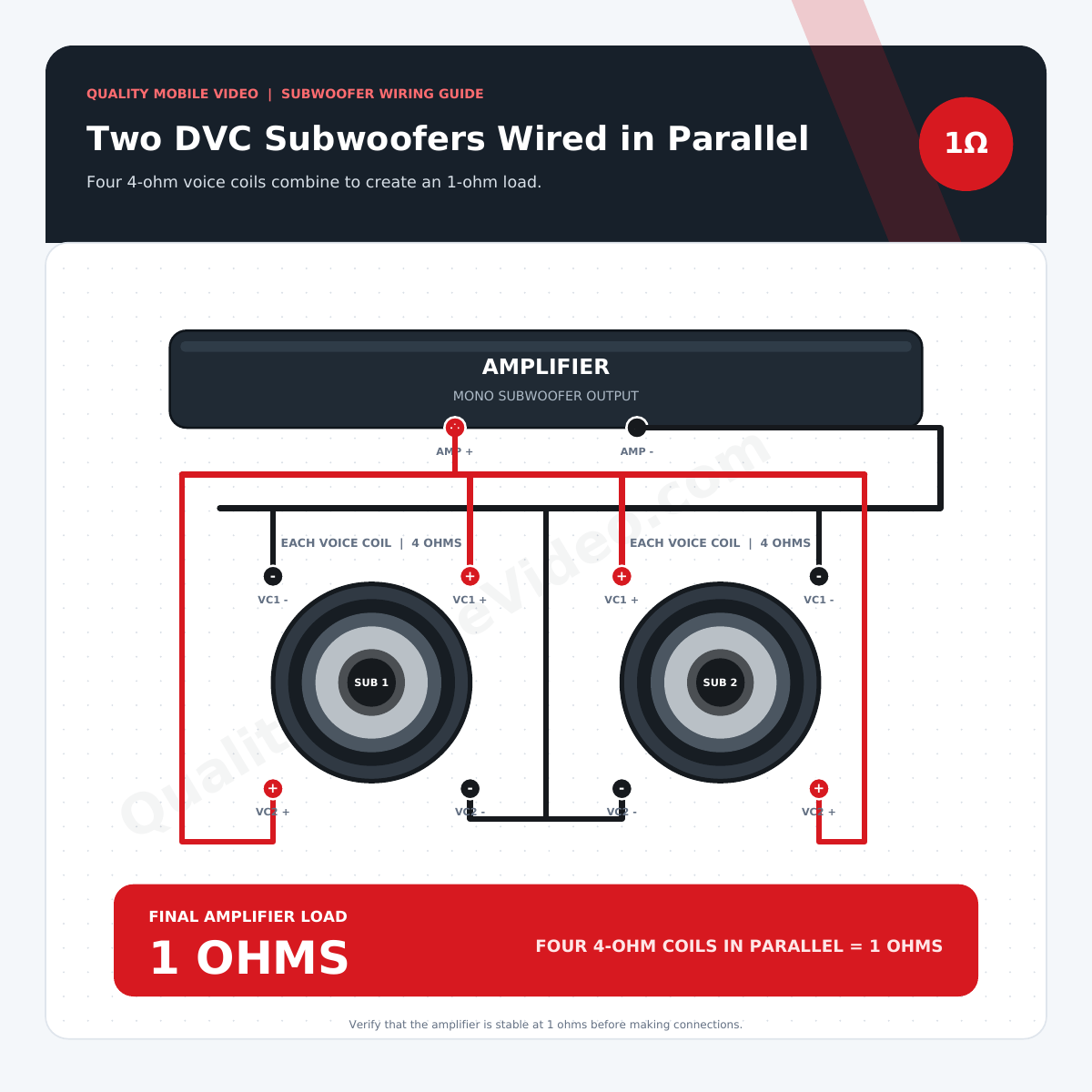
Four 4-Ohm Coils in Parallel
Wire all four 4-ohm voice coils in parallel to present a nominal 1-ohm load to the amplifier.
View the 1-ohm wiring guide →Parallel-wiring impedance chart
| Subwoofer type | Parallel calculation | Final amplifier load | Amplifier consideration |
|---|---|---|---|
| Two dual 2-ohm DVC subwoofers | 2Ω ÷ 4 coils | 0.5Ω | Requires a specialized monoblock explicitly stable at 0.5 ohms. |
| Two dual 4-ohm DVC subwoofers | 4Ω ÷ 4 coils | 1Ω | Use a monoblock with a published 1-ohm RMS rating and minimum load. |
How two DVC subwoofers are wired in parallel
-
01
Verify both subwoofers
Confirm that both drivers are matching DVC models and verify the impedance of every coil from the label, manual, or specifications.
-
02
Connect all positive terminals
Join both positive voice-coil terminals on each subwoofer, then connect the positive groups from both subwoofers to a common positive point.
-
03
Connect all negative terminals
Join both negative voice-coil terminals on each subwoofer, then connect the negative groups from both subwoofers to a common negative point.
-
04
Connect and test the amplifier leads
Connect the common positive and negative points to the matching amplifier outputs, then measure the completed circuit before powering up.
Shop subwoofer wiring essentials
Select the correct subwoofer and amplifier first, then use properly sized wire, circuit protection, and signal cables to complete a safe, reliable installation.
Car Subwoofers
Shop subwoofers by size, impedance, power handling, and enclosure type.
Shop subwoofers →Monoblock Amplifiers
Choose a dedicated subwoofer amplifier that matches the final load and RMS power.
Shop mono amplifiers →Speaker Wire
Find stranded speaker wire in the gauge and length required for your installation.
Shop speaker wire →Amplifier Wiring Kits
Get power wire, ground wire, circuit protection, RCA cables, and installation hardware.
Shop amplifier kits →RCA Audio Cables
Use quality shielded interconnects to carry the low-level signal to the amplifier.
Shop RCA cables →Fuses & Power Distribution
Protect the amplifier power cable and distribute current safely throughout the system.
Shop circuit protection →Two-DVC parallel-wiring FAQ
Why does parallel wiring lower the final impedance?
Parallel branches provide additional paths for current. With four identical coils, the final nominal impedance equals one coil’s impedance divided by four.
Why does my multimeter read less than the calculated load?
A multimeter measures DC resistance, while the subwoofer specification is nominal AC impedance. DC resistance is normally lower than the listed nominal impedance.
Can I operate only one voice coil on either subwoofer?
All four voice coils should be connected as intended by the manufacturers. Leaving a coil disconnected can change performance and power handling and may damage the subwoofer.
Will both subwoofers receive the same power?
Two matching subwoofers with balanced wiring will divide the amplifier’s output approximately equally. Compare half of the amplifier’s RMS output with the RMS rating of each driver.
